


Cryostat Window, Filter and Dichroic Specification and Measurements
For the latest on the SCUBA-2 filters we refer you to:
Jamie L. Cookson, Dan Bintley, Shaoliang Li, Peter A. R. Ade, Rashmikant Sudiwala, Carole Tucker, “Upgrading SCUBA-2 with a newly designed thermal filter stack,” Proc. SPIE 10708, Millimeter, Submillimeter, and Far-Infrared Detectors and Instrumentation for Astronomy IX, 1070839 (9 July 2018); https://doi.org/10.1117/12.2313018
Introduction
This document details the specifications for the SCUBA-2 cryostat window, filters and dichroic. It also includes measured plots for the final individual filters at room temperature. The measured profiles of the operational instrument as measured with the FTS is also shown. The general philosophy has been to adopt a scheme in which the instrument is over-filtered, i.e. extra provision is made for filters at critical apertures, although some of these may later prove unnecessary. There has been an optimization procedure for the entire filter chain to maximize transmission (e.g. relative fringing between filters) and minimize out-of-band radiation.
There was a change to the filters made at the end of 2016. A new design thermal blocking filler was tested and then installed in SCUBA-2 ( Cookson 2018). The new versions of the double-sided thermal filters have a modified geometry to improve the reflectivity of these layers and more efficiently reject the unwanted SW radiation. In addition, a newly designed 55cm -1 LPE with better in-band transmission was installed to replace the existing 37cm -1 LPE.
Pre 2017 Estimated Filter profiles
The profiles of the SCUBA-2 filters have been measured individually at Cardiff. The text files linked below contains the total profile obtained by stacking all the measurered filter profiles togheter, including the cryostat window and the dichroic. Some of the IR edge blocking filters have been estimated from higher frequency data. These filters are not expected to contibute to the profile since they are flat over the bandpass filters but it will affect the total transmission. No attempts have been done to include losses in mirrors or due to scattering. The filter measurements has been done at room temperature – not the operating temperature. Further, any fringing due to reflections between filters in the cryostat is not taken into account. The actual profile in the instrument will be measured when the SCUBA-2 FTS is operational.
The predicted bandpass profiles can be downloaded form the links that follows – note these files have an extension of pdf but are txt files (wordpress don’t allow uploading of text files) – so use the browser to download the files – do not click on the link to open them.
850: model850
450: model450
Measured performance in operation.
The bandpass profiles has been measured with the FTS-2 on the telescope with SCUBA-2 operating as during normal observing. Since the FTS-2 only uses parts of the arrays s8c, s8d, s4a and s4b only profiles for part of these arrays can be measured. The averaged profiles for s8c and s8d are shown below. The y-scale is arbitrary and the green lines are variance computed form the variation over the used part of the array. For a SCUBA-2 map the effective bandpass profile in a reduce map pixel is a weighted average from the profiles across the array. The weighting will depend on the position in the map.
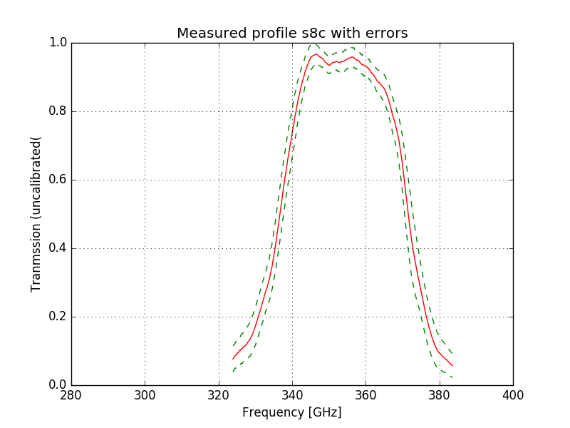
The s8d arrays shows fringing of unknown origin. This is not understood since the optical path for s8c and s8d are almost identical.
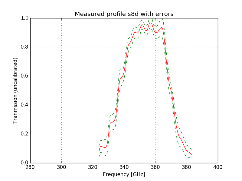
The most obvious difference between the measured and predicted bandpass is a shift upwards by 0.1 cm-1 for the 850 micron band. For details see SPIE_2014_SCUBA-2_filters_paper. Fires with the numerical data are can be downloaded from the following links. Note these are text files but given the extension pdf to defeat the security (upload/download of txt files not allowed). Use you browser to download the file – do not open it by just clicking on the file.
s8c: s8c20140313_00004-20140313_00002_SFP_scaled_spec_average_v2
s8d: s8d20140313_00004-20140313_00002_SFP_scaled_spec_average_v2
Specifications
The filter and dichroic specifications are detailed in the following tables:
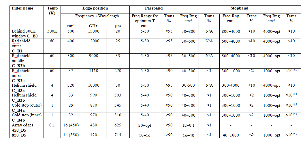
Low- and high-pass edge and thermal filters
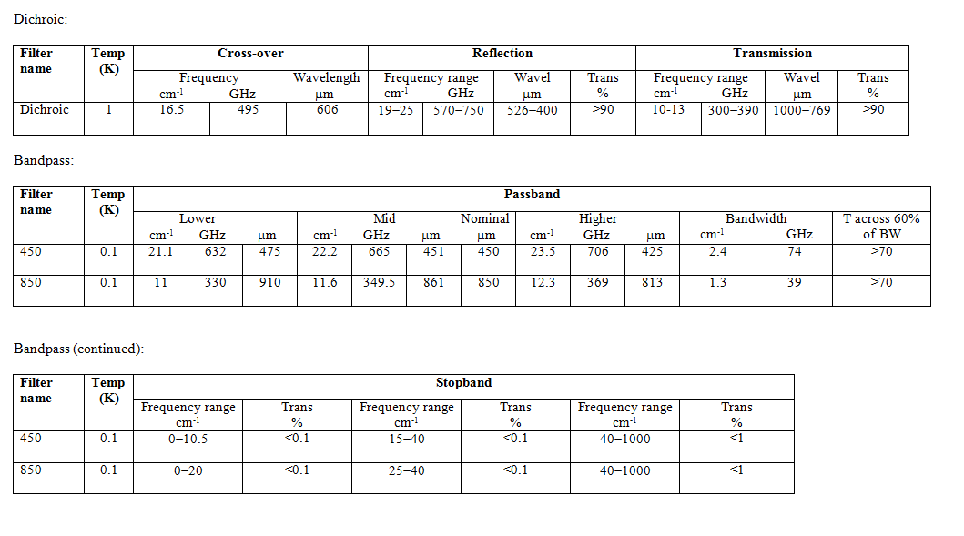
Dichroic and Bandpass
Window
Filter descriptions, sizes, clear apertures and measurements
Window Protector
Dimensions: clear aperture diameter 235mm, outer diameter 245mm, 4um thick.
Cryostat window
UHMW polyethylene with anti-reflection coating to maximize transmission at 450 and 850um. Dimensions: clear aperture diameter is 200mm, outer diameter 255mm, and 8.63mm thick. Transmission data for the UHMW polyethylene window are given in the image below:
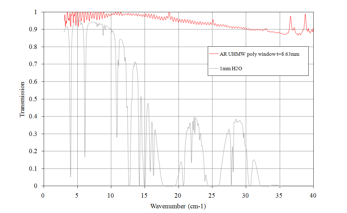
Transmission of the AR coated UHMW polyethylene window material for 8.63mm thickness.
C_B0: 300 K filter behind cryostat window
5um thermal filter Dimensions: clear aperture diameter 200mm, outer diameter 210mm, 4um thick.
C_B1: Radiation shield (outer) filter (60K)
10um thermal filter Dimensions: Clear aperture diameter 185mm, outer diameter 195mm, 4um thick.
C_B2b: Radiation shield (middle) filter (60K)
20um thermal filter Dimensions: clear aperture diameter 185mm, outer diameter 195mm, 0.4um thick.
C_B2a: Radiation shield (inner) filter (60K)
37cm-1 LPE Dimensions: clear aperture diameter 185mm, outer diameter 195mm, 0.65mm thick.
C_B3a: Helium shield (outer) filter (4K)
30um thermal filter Dimensions: clear aperture diameter 185mm, outer diameter 195mm, 0.4um thick.
C_B3b: Helium shield (inner) blocking filter (4K)
33cm-1 low-pass edge Dimensions: clear aperture diameter 185mm, outer diameter 195mm, ~0.6mm thick.
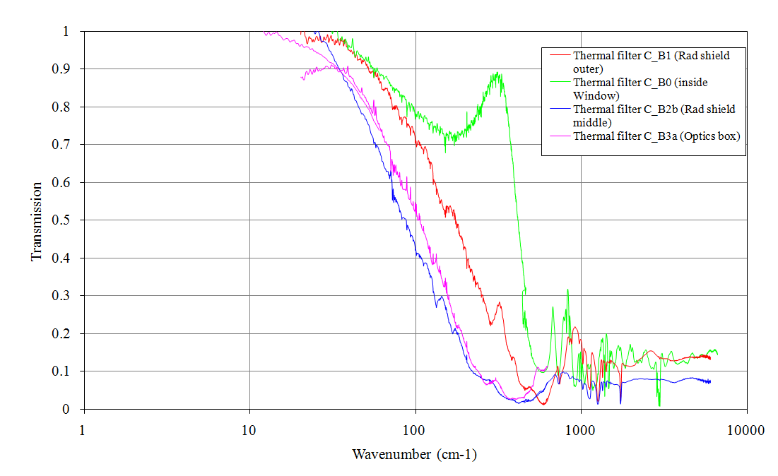
Thermal filters. C_B0, C_B1, C_B2b and C_B3a. The effect of poor signal to noise is visible in the low frequency data – the real transmission from 0 to 10 cm-1 is over 0.99.
C_B4a: Cold stop blocking (outer) filter (1K)
29cm-1 low-pass edge Dimensions: clear aperture diameter 102mm, outer diameter 117mm, ~0.6mm thick. This is the filter that was added in December 2007 and is the outer filter at 1K, i.e. closest to the cold shutter.
C_B4b: Cold stop blocking (inner) filter (1K)
32cm-1 low-pass edge Dimensions: clear aperture diameter 102mm, outer diameter 117mm, ~0.6mm thick.
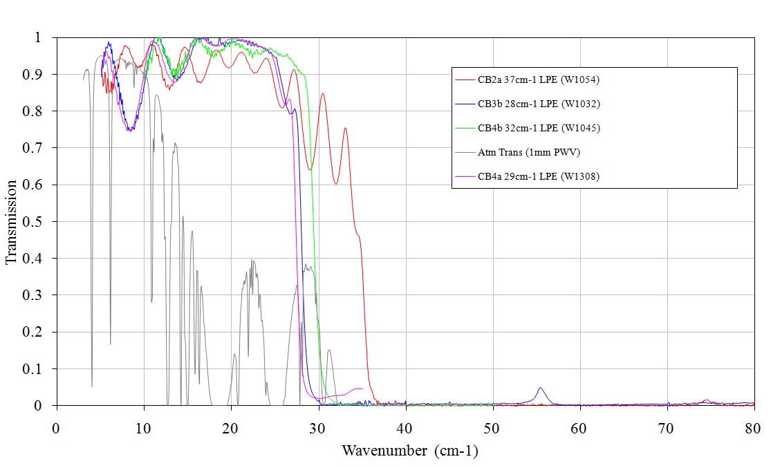
Instrument blocking filters. CB2a (W1054), CB3 (W1032) and CB4 (W1045).
Dichroic (1K)
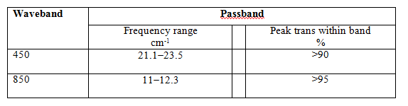
16.5cm-1 low-pass edge. This filter is designed to transmit (>90%) the 850um band, whilst reflecting (>90%) the 450um band. The prototype tests showed the dichroic to be effective in both reflection and transmission at 30 degrees incidence for both s- and p-polarizations. Dimensions and angle of incidence: clear aperture diameter 145mm with an angle of incidence of 35 degrees. Filter thickness ~1mm.
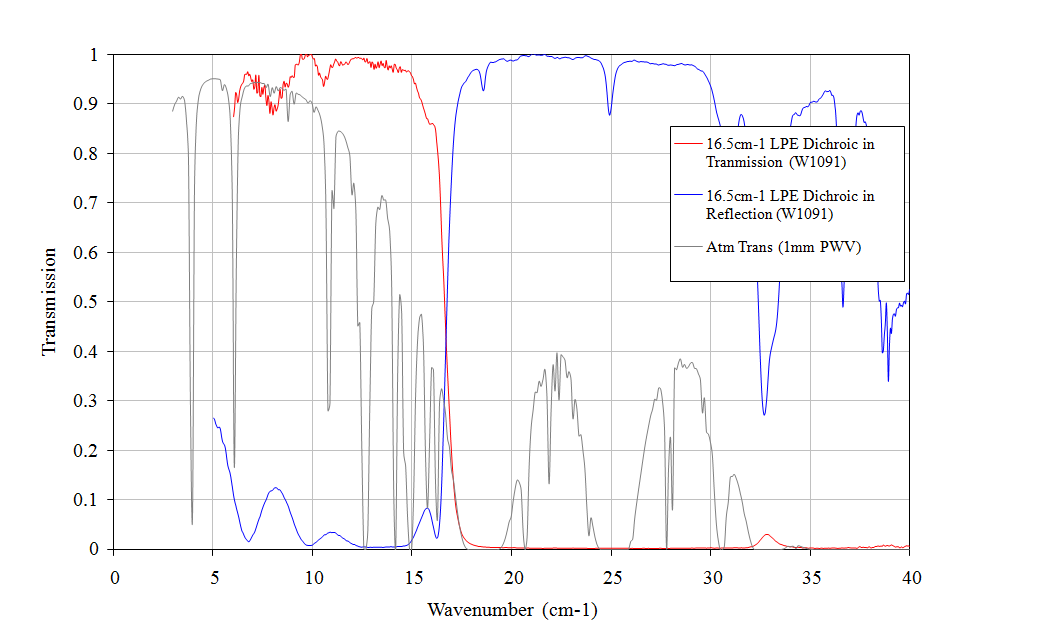
Measured transmission and reflection data for W1091 dichroic.
B5: Arrays edge filters (1K)
Both arrays will have an additional blocking filter to eliminate any higher-frequency leaks. 450_B5 16cm-1 high-pass edge and 26cm-1 low-pass edge. See figure 5. 850_B5 14cm-1 low-pass edge See figure 6. Dimensions: clear aperture diameter 110mm. Note the 450 edge has changed to two filters, both a low-pass and a high-pass, for the new narrower bandpass.
BP: Bandpass filters (1K)
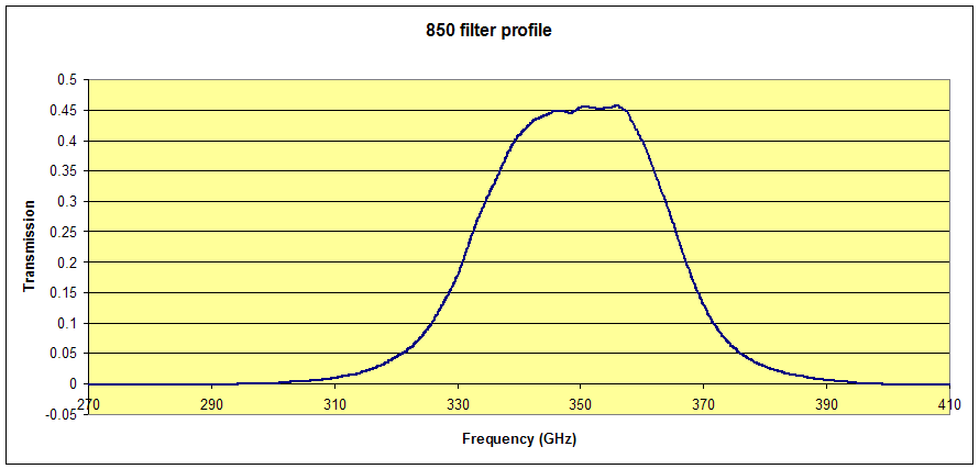
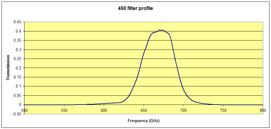
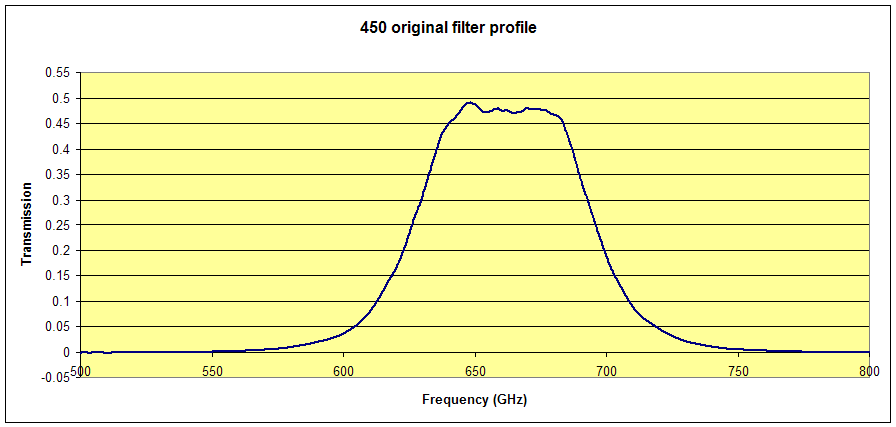
The passbands and cut-offs for these filters are derived from the atmospheric model for 1mm of PWV. They are of the hot-pressed technology. 450_BP 450um BP See figure 5. Note: The 450 bandpass was changed to a narrower version following the first on-sky tests. The plot showes the installed narrowed 450um bandpass. The 26cm-1 low-pass edge filter is not shown in the figure. 850_BP 850um BP See figure 6. Dimensions: clear aperture diameter 110mm.
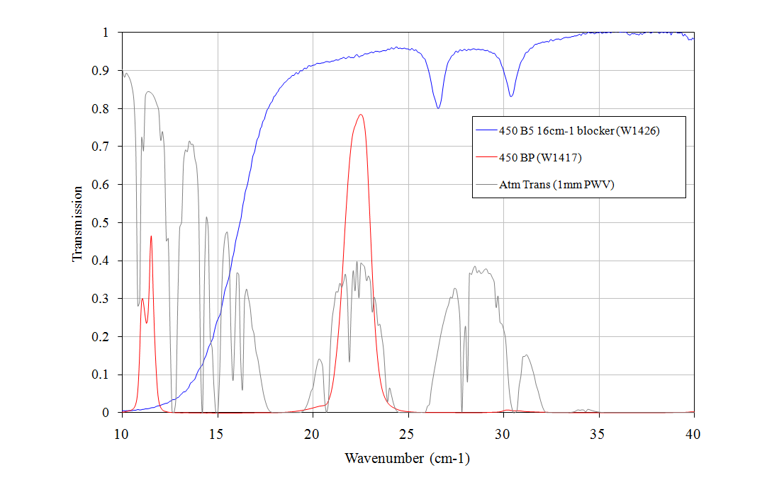
Array filters for 450um band. 450 BP (W1417) and 450 B5 16cm-1 HPE (W1426). The LPE (W1058) is not shown, and will be added.
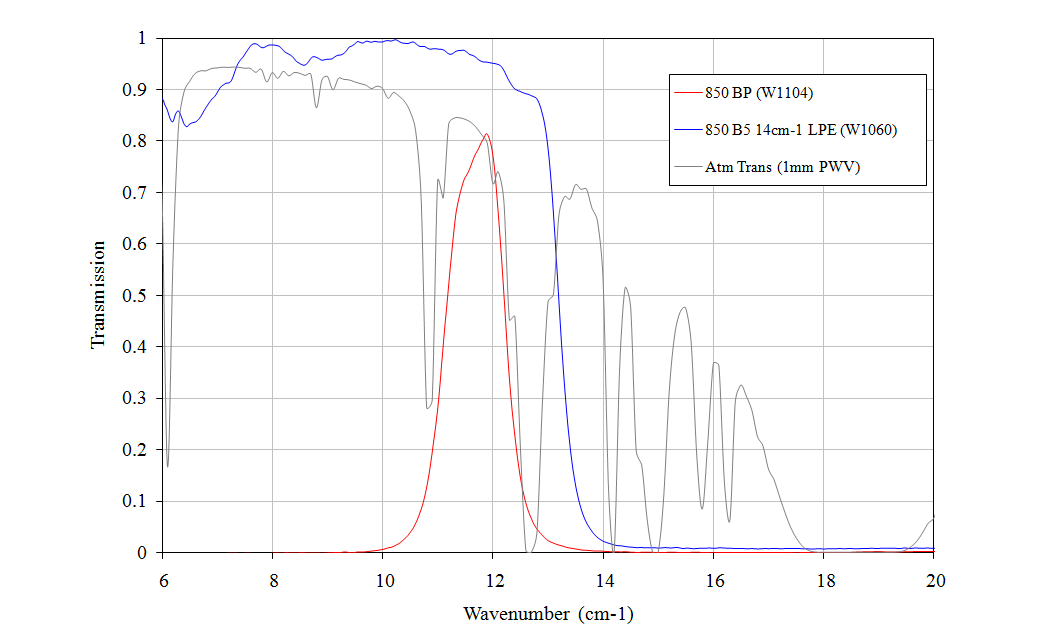
Array filters for 850um band. 850 BP (W1104) and 850 B5 14cm-1 LPE (W1060).