


Pointing and focus observations are made throughout the night to ensure optimal telescope performance. Point and focus observations are obtained towards sources chosen from the JCMT Pointing Catalogue. For heterodyne work we mainly take CO spectra of bright asymptotic giant branch stars; for SCUBA-2 work we take images of (mainly) blazars.
Pointing
When coordinates are inserted into the TCS (telescope control system) the telescope slews to them, if the telescope were perfect it would slew immediately to this position. However structural imperfections mean that it doesnt end up at the requested coordinates. A pointing model is used to describe these imperfections and correct for them so when a certain position is requested the telescope can point at it to reasonable accuracy.
Pointing logs
Each night, pointing data is logged in a file called POINTING.log. This file contains many variable describing the state of the telescope and the source but the key values are;
- Az El coordinates of source
- K-mirror parameters
- UAZ and UEL
- DX and DY
Where UAZ and UEL are the absolute offsets from the current model for that instrument in arcsecs. DX and DY are the relative offsets from the previous poitning values (i.e. if obs #01 gives UAZ, UEL = +2, +3, then obs #02 gives UAZ, UEL = -1, -5, then DX, DY for obs #2 will be -3, -8).
Any systematic errors in the pointing model will generate large-scale error patterns over the sky. Pointings need to be made, therefore, often enough to follow and compensate for these errors. In practice, this is well accomplished by hourly pointings when a science field is being observed for multiple hours (‘tracked’), but certainly a new pointing is required before each new science observation.
Heterodyne pointing example
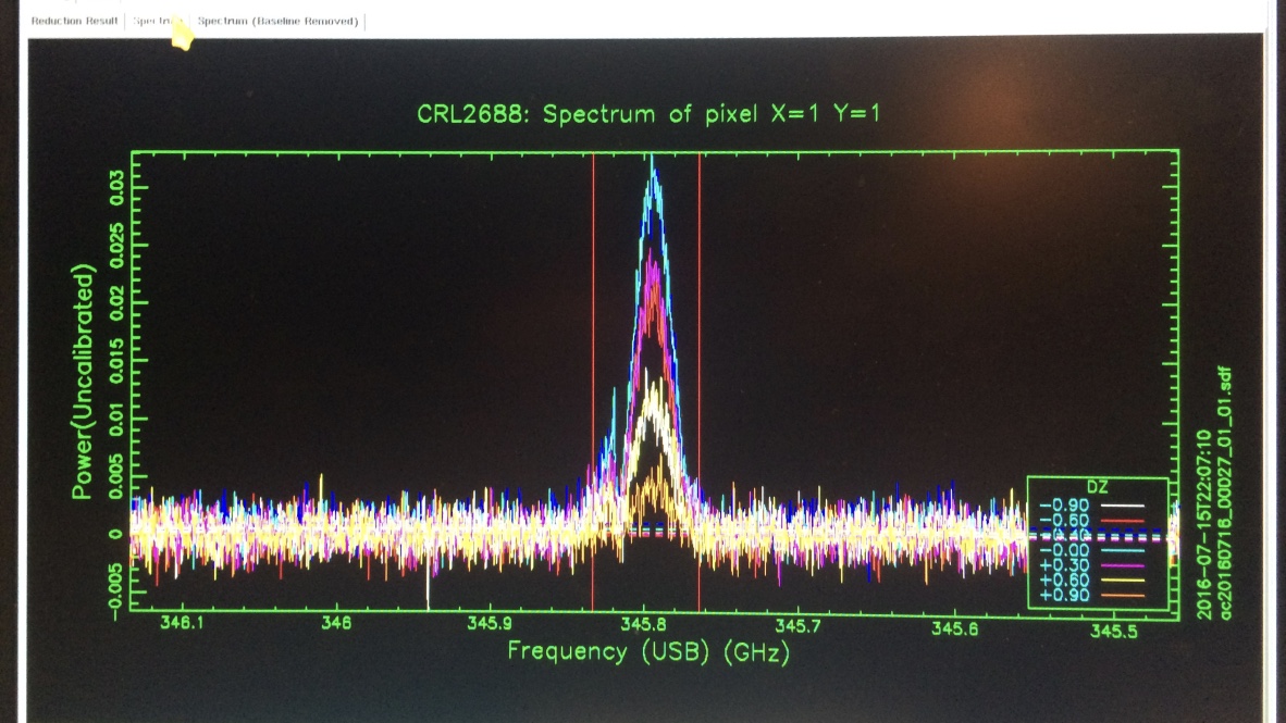
observations are made by taking spectra in the direction of the nominal position of source and then towards four positions offset by half of the beamsize. (Heterodyne pointing and focus observations are not calibrated by hot and cold load measurements).
The results of an example (HARP) pointing experiment are shown below. The inset (blue) spectra correspond to the positions within the ‘five-point’ indicated by the small arrow. The color scale used in displaying the fivepoint usually relates white with the strongest spectral line strength
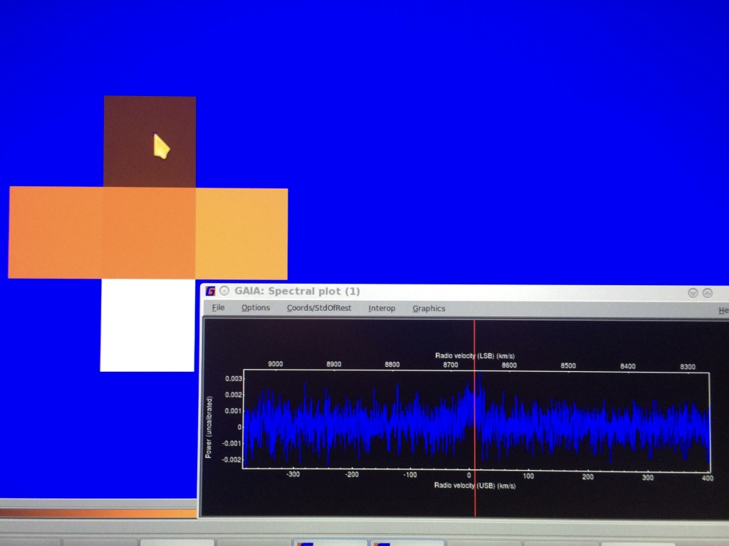
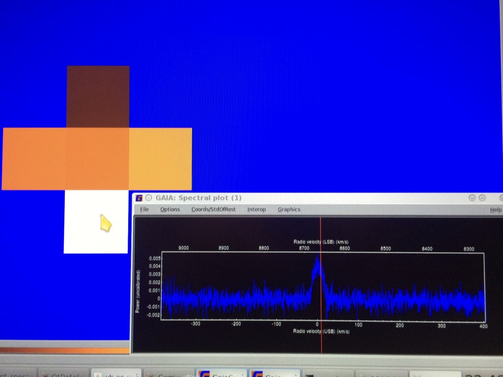
The line appears strongest in the bottom-most of the 5 positions. The extent of the line is contributed interactively by the TSS (see the red vertical lines in the figure below):
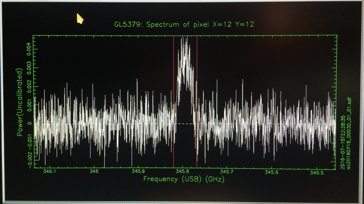
. . and the pointing software derives the line intensities at each of the 5 positions and fits a Gaussian in both directions to determine the location of the peak line strength
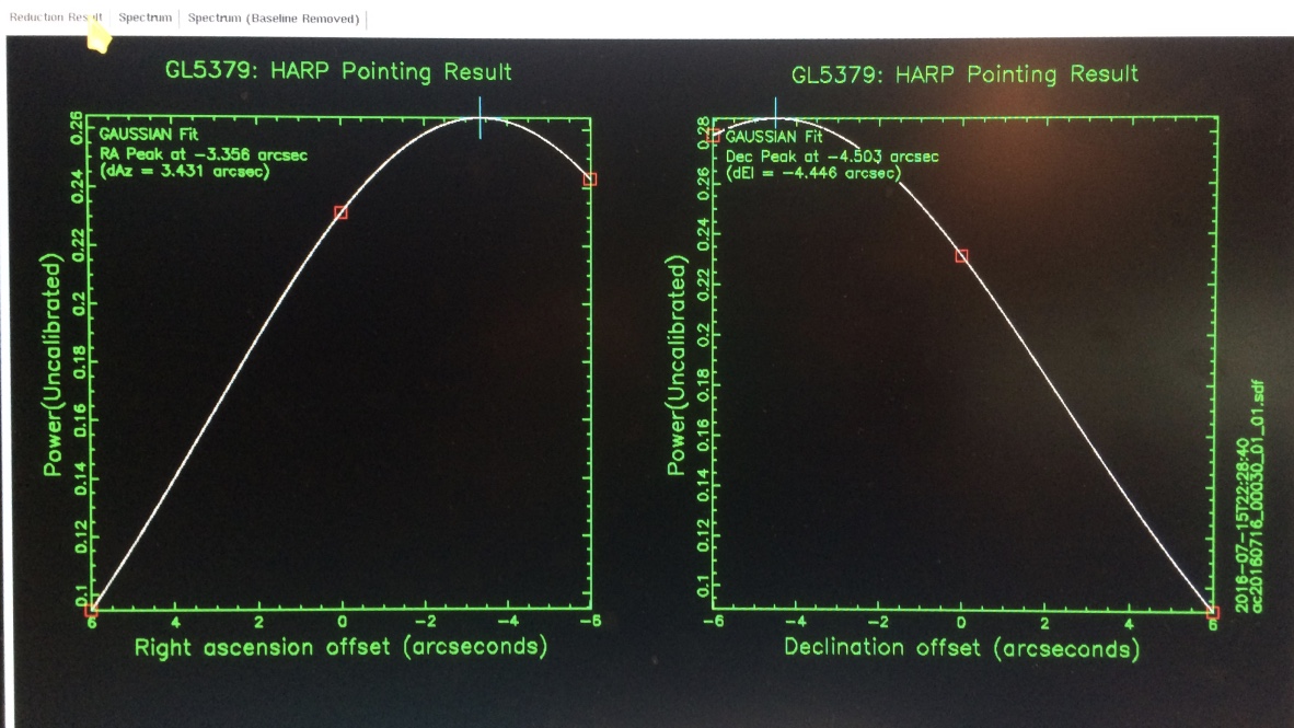
The resulting pointing correction is then applied.
FOCUS
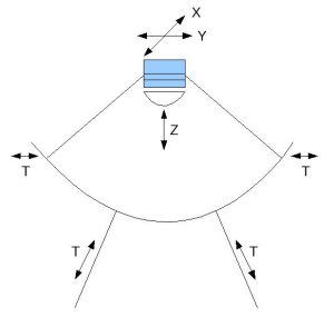
Focussing the telescope essentially involves moving the SMU to the optimal in-focus position. The focus can be adjusted in 3 dimensions – x and y which move parallel to the elevation axis (x) and perpendicular to it in the same plane (y), then the z axis moves the SMU in and out of the dish itself.
The Focus Model
The focus model encompasses a number of contributing factors that determine the best position of the SMU. These are:
- zero-point offset
- instrument-dependent offset
- elevation dependent offset
- temperature dependent offset
These values are used to give to a reasonable fit over the sky (just like the pointing model). But also like the pointing model it is not perfect so regular focuses (or pointings) need to be done to refine the SMU position and correct for inaccuracies.
Focus observation
Movement in the Z axis varies most throughout the night and is checked most often. During a focus observation, spectra are taken with the secondary mirror at each of 7 positions spaced by 0.3mm along the Z-axis, which is the direction between the primary and secondary surfaces. The spectral line is recorded at each position.
and the integrated line strength of each spectrum is extracted by the fitting of a Gaussian to the resulting (uncalibrated) intensity values. A curve is then fitted with the SMU position at the peak representing the optimal position of the SMU along that axis – where the signal strength is the strongest.
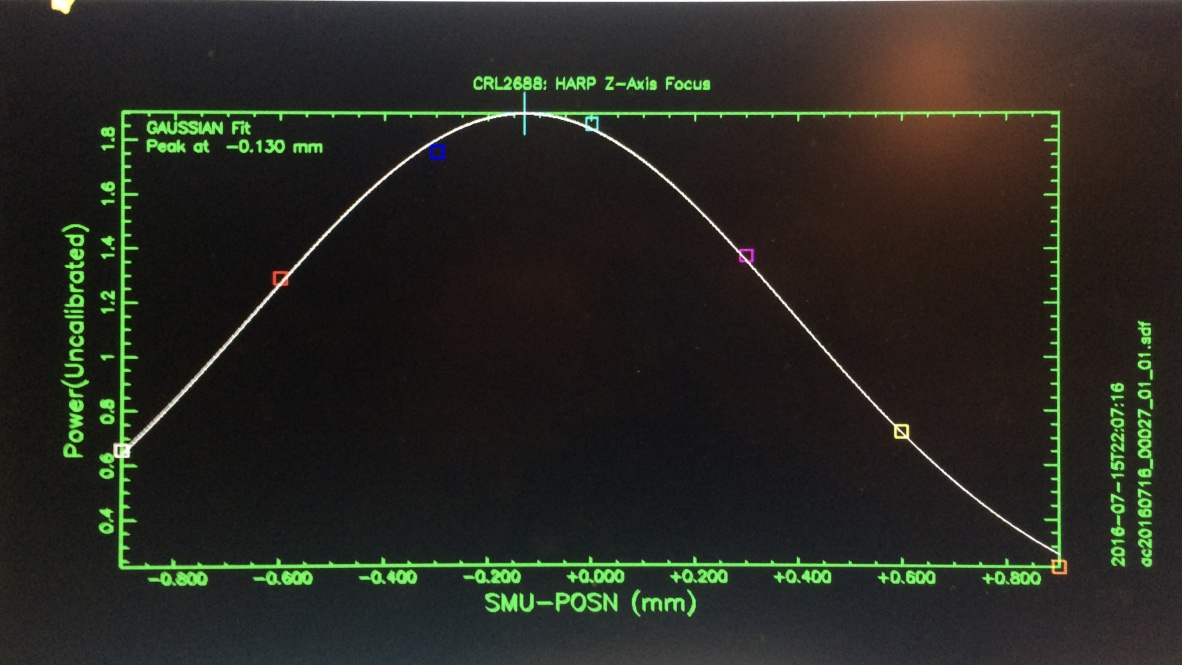
Similar observations when adjusting the SMU position (by 1.0mm) along the X- (up-down) and Y- axes allows for total optimization of the SMU configuration (‘focus’!). We typically do ‘focusses’ in Z, X & Y at the start of every night, again after 2 and maybe 4 hours, but less frequently in the second half of the night as the telescope settles, thermally.
In Z we aim to be within about lambda/10 or about 0.1 mm, noting that 0.3 mm ~ lambda/4 is a significant offset. In X and Y we are less sensitive – our standard step is 1 mm or about lambda. After 3 steps the signal is almost gone. So in these cases you would like to be better than say lambda/3 or so.
Temperature considerations
Z focus changes most at the beginning and end of the night when the temperature changes most rapidly. The support arms for the SMU have a 0 thermal expansion efficient, however the dish itself does expand and contract. As temperature rises the dish expands outwards and the SMU is pulled inwards; as it contracts the SMU is pushed upwards.
There is a corrective term which compensates for change in the Z focus due tot expansion of the dish. Unfortunately this value is currently determined using the mean leg temperature rather than the actual dish temperature. The concern is that there is lag in the temperatures with the thin dish responding much more quickly to changing temperature than the thick legs.
 Focus impact on pointing

Changing the x and y focus necessarily affects the pointing of the telescope. There is a fixed relationship between the mm moved in x/y and the pointing offset, with 1mm = 24.56″. When a change is made to the X or Y focus, the TCS automatically adjusts the position of the telescope to compensate for the change in pointing. This happens when the results of a focus observation are accepted. If one were to change the X or Y collimations in the engineering files, this automatic compensation would not be made and a large pointing shift would be expected.
Collimations
Each instrument has focus collimation terms or the ‘instrument-dependent offset’. If the receiver cabin were perfect and each receiver was optimized to receive from the center of the TMU then these would not be necessary. However each receiver has its own spot on the TMU which feeds the beam into it and the adjustments in collimations reflect this. These collimaton terms are kept in the intrument.ent files at the summit.
SCUBA-2 pointings
are short daisy observatons analyzed for the image centroid.